

How to Design a Purified Water Distribution Loop: Velocity, Temperature and Sanitisation
- Blog
- How to Design a Purified Water Distribution Loop: Velocity, Temperature and Sanitisation
How to Design a Purified Water Distribution Loop: Velocity, Temperature and Sanitisation
Table of Contents
- What is a Distribution Loop?
- Flow Velocity
- Temperature Selection
- Avoiding Dead Legs
- Drainability and Slope
- Material and Surface Quality
- Sanitization Methods
- Monitoring and Sampling
- Planning Point-of-Use Locations
- Frequently Asked Questions
- Conclusion
In pharmaceutical, biotechnology, and cosmetics facilities, purified water and water for injection (WFI) are among the most critical production inputs. Maintaining water quality all the way to the point of use is just as important as producing high-quality water itself. This vital role is fulfilled by the distribution loop. An inadequately designed loop can lead to microbial contamination and quality deviations, regardless of how advanced the generation system is. In this article, we examine the fundamental design principles of purified water distribution loops.
What is a Distribution Loop?
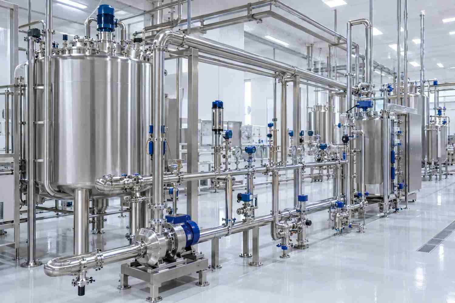
A distribution loop is a closed piping system through which purified water exits the storage tank, circulates through points of use, and returns to the tank. Water is maintained in continuous motion. Because stagnant water provides an ideal environment for microbial proliferation and biofilm formation, the primary goal of loop design is to ensure water never remains static at any point for extended periods.
A typical loop comprises a storage tank, distribution pump, heat exchangers, points of use, return line, measurement and control instrumentation, and sanitization equipment.
Flow Velocity
Maintaining water flow above a designated minimum velocity throughout the loop promotes turbulent flow and hinders biofilm adherence on pipe walls. Crucially, adequate velocity must be preserved in the return line even during peak consumption. Consequently, pump capacity must be calculated to ensure target return-line velocity when all points of use are fully operational. Continuous monitoring of flow rate on the return line verifies that this condition is maintained throughout operation.
Selecting appropriate pipe diameters plays a decisive role in achieving target velocities. Oversized piping results in lower fluid velocity for a given flow rate, while undersized piping increases pressure drop, driving up pump head requirements and energy consumption. Therefore, reducing pipe diameters in downstream sections of the loop as flow rate decreases past points of use can be evaluated. Performing calculations during the design phase and validating the hydraulic model prior to installation prevents costly setbacks during commissioning.
Temperature Selection
Purified water loops are generally categorized into three thermal operational regimes: hot, ambient, and cold loops. Hot loops are widely utilized in water for injection (WFI) systems, as elevated temperatures inherently provide continuous microbial control. Ambient loops offer energy efficiency benefits but require periodic sanitization. If cold water is required at specific points of use, localized point-of-use coolers or dedicated cold sub-loops can be implemented rather than chilling the entire main distribution loop.
Avoiding Dead Legs
Take-offs between point-of-use valves and the main header represent potential stagnation zones. These branches must be kept as short as possible. Best practice dictates positioning the point-of-use valve directly on the main header or using an exceptionally short tee connection. For this purpose, zero-static valve bodies welded directly into the main run are widely specified. The same design rule applies to sensor connections, sampling points, and drain branches.
Drainability and Slope
Full drainability of the distribution loop is essential for maintenance, inspection, and sanitization. Piping runs must be installed with continuous pitch toward designated low-point drain valves. A self-draining system simplifies safe re-commissioning, particularly after extended operational shutdowns.
Achieving proper pitch is straightforward in CAD design but demands strict attention during site installation. If pipe supports are incorrectly set or if piping sags between supports, runs that appear properly pitched on drawings can form water-trapping pockets on-site. Therefore, measuring and documenting pipe slopes after installation is strongly recommended.
Material and Surface Quality
AISI 316L stainless steel is the standard material for distribution loops. Low interior surface roughness minimizes biofilm attachment. Joints are executed using automated orbital TIG welding and inspected via borescope. Following installation, the complete loop undergoes passivation. These steps are equally vital for mitigating the risk of rouging and ensuring long-term system integrity.
Sanitization Methods
Periodic sanitization is conducted to maintain microbial control across the distribution loop. Common methods include:
- Thermal sanitization: Heating the water circulating in the loop to high temperatures for a specified dwell time.
- Ozone sanitization: Utilizing dissolved ozone within the storage tank and loop, followed by UV destruction prior to point-of-use delivery.
- Chemical sanitization: Disinfecting the loop using approved chemical agents, followed by thorough rinsing.
Selecting the appropriate method depends on loop operating temperature, material compatibility, operational scheduling, and available facility utilities.
Monitoring and Sampling
Loop performance is continuously monitored using critical analytical parameters including conductivity, total organic carbon (TOC), temperature, flow rate, and pressure. Additionally, routine microbiological testing is performed on samples taken from points of use. Installing sample valves at representative loop locations and defining robust sampling protocols are essential to ensuring the reliability of analytical monitoring data.
Planning Point-of-Use Locations
The quantity and spatial arrangement of points of use directly influence loop sizing and hydraulic balance. Required flow rates, temperatures, usage frequencies, and simultaneous demand scenarios must be defined during the design phase. Building planned spare capacity into the loop for future point-of-use additions minimizes the cost of subsequent modifications that could alter loop qualification status. SS Proje validates loop routing and hydraulic balance prior to installation using 3D design and flow analysis.
Frequently Asked Questions
How long can a distribution loop be?
There is no fixed maximum length; however, longer loops increase pressure drops, pump capacity requirements, and temperature control complexity. In expansive facilities, designing multiple main loops or sub-loops is often more practical.
Can a new point of use be added to an existing loop?
Yes, additions are possible. However, any modification must be formally evaluated for its impact on hydraulic balance, dead-leg compliance, and qualification status, and managed through the facility's change control procedure.
Can plastic piping be used in purified water loops?
Suitable polymer piping systems may be used in specific purified water applications. However, stainless steel remains the preferred choice for hot loops, thermal sanitization, and water for injection (WFI) systems.
A purified water distribution loop is an integrated system where flow velocity, operating temperature, dead-leg minimization, surface finish, and sanitization strategy must be evaluated holistically. Robust design ensures water quality is preserved up to the point of use and confidently defended during regulatory audits. Contact us to learn more about our water systems engineering and projects.