



Instrumentation in Process Tanks: Level, Temperature and Pressure Measurement
- Blog
- Instrumentation in Process Tanks: Level, Temperature and Pressure Measurement
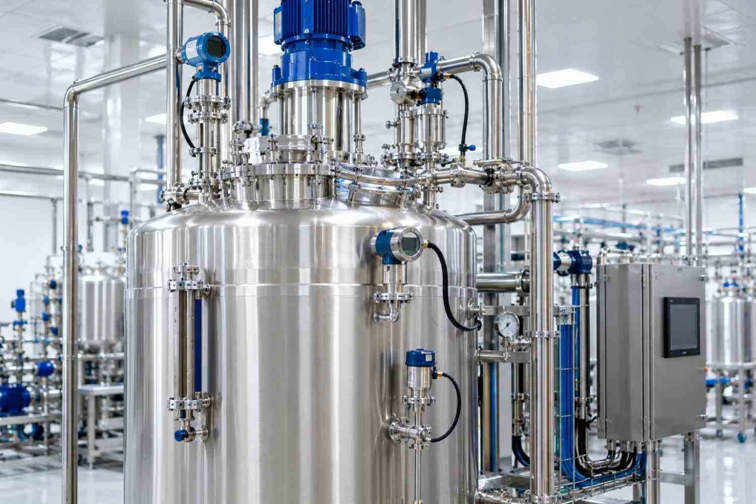
Instrumentation in Process Tanks: Level, Temperature and Pressure Measurement
Table of Contents
- What is Measured in Process Tanks?
- Level Measurement
- Temperature Measurement
- Pressure Measurement
- Hygienic Connection Details
- Location Selection and Cleaning Coverage
- Calibration and Verification
- Integration with Control Systems
- Common Issues
- Frequently Asked Questions
- Conclusion
The safe and efficient operation of a process tank depends on accurately knowing what is happening inside. How much product is in the tank, at what temperature, and under what internal pressure? Instrumentation provides the answers to these questions. In hygienic process tanks, selecting the correct measuring instruments, installing them properly, and calibrating them regularly are critical for both product quality and cleanability. In this article, we cover the primary measurements used in process tanks and key points to consider.
What is Measured in Process Tanks?
The core variables typically measured in a process tank are level, temperature, and pressure. Depending on process requirements, additional parameters such as weight, conductivity, pH, dissolved oxygen, or turbidity may also be monitored. The objective of each measurement must be clearly defined: whether an instrument is intended for control, monitoring, alarms, or safety functions directly influences device selection.
Level Measurement
Level measurement determines the volume of product within the tank, controls filling and emptying sequences, and prevents operational risks such as overfill or dry running. Common methods in hygienic applications include:
- Hydrostatic Measurement: Calculates liquid height based on hydrostatic head pressure at the bottom of the tank. It is simple and reliable, though density variations require compensation.
- Radar Measurement: Operates contactlessly. Suitable non-contact or guided radar models can be selected for challenging conditions with foam or vapor. Non-contact operation provides clear hygienic benefits.
- Load Cell Weighing Systems: The tank is mounted directly on load cells to measure mass. Preferred in applications requiring precise batch recipe control.
- Level Switches: Trigger discrete signals upon reaching defined high or low thresholds; typically utilized for high/low level alarms and pump run-dry protection.
Temperature Measurement
Temperature is a vital process variable affecting product quality, reaction kinetics, solubility, and microbiological safety. In process tanks, temperature is most commonly measured using Resistance Temperature Detectors (RTDs). Positioning the sensor in a representative location is essential; mounting too close to a heating/cooling jacket or in a poorly agitated zone leads to inaccurate process readings. In hygienic applications, sensors are typically installed within hygienic thermowells, allowing calibration or replacement without breaching the process boundary.
Pressure Measurement
Pressure measurement is used to monitor internal pressure in vessel spaces, control vacuum or pressurized operations, manage safety functions, and assist in hydrostatic level calculations. Hygienic pressure transmitters utilize flush-mounted diaphragms in contact with the product. A flat, crevice-free diaphragm surface is essential for cleanability. Resistance to sterilization temperatures and measurement stability during thermal cycles must also be evaluated during instrument selection.
Hygienic Connection Details
How an instrument connects to the vessel is as critical as the instrument itself. Hygienic instruments are typically mounted using sanitary clamp fittings or dedicated hygienic process connections. Connection nozzles must be kept short to position the sensing diaphragm flush with the internal vessel wall. Long nozzles create dead legs where cleaning solutions cannot circulate effectively.
Location Selection and Cleaning Coverage
Instrument nozzle locations must be coordinated alongside spray ball positioning during initial tank design. Cleaning fluid discharged from spray devices must reach internal nozzle recesses and sensor faces. Furthermore, non-contact instruments such as radar level transmitters must have an unobstructed beam path, free from agitator blades, internal piping, or fill lines. Deciding nozzle layout during design prevents costly physical modifications on the shop floor.
Calibration and Verification
Regular calibration of critical instruments maintains measurement precision and regulatory compliance. Calibration intervals depend on instrument criticality, manufacturer guidelines, and historical performance data. Utilizing removable sensor inserts and hygienic quick-disconnect fittings enables calibration without compromising tank sterile boundaries or extending downtime. Calibration records form a mandatory component of qualification and audit documentation, particularly in pharmaceutical manufacturing.
Integration with Control Systems
Instrument signals are transmitted to the facility control system (DCS or PLC) for automated process execution, alarm management, and data logging. Signal protocols, measurement spans, alarm thresholds, and fail-safe states must be defined early in design. The instrument index and P&ID serve as master references for managing this data consistently. For regulated processes, data logging frequency, retention policies, and data integrity compliance (e.g., 21 CFR Part 11) must also be addressed.
Common Issues
Frequent field issues include installing sensors in unrepresentative stagnant zones, radar signal interference from internal vessel internals, uncompensated density shifts in hydrostatic level units, dead-leg cleaning challenges from long nozzles, and requiring full vessel shut-downs for routine calibration. The majority of these issues are eliminated by co-designing instrument layouts alongside the vessel itself.
Field cabling and junction box placement within hygienic processing areas are also frequently overlooked. Cable glands must provide reliable seals, junction boxes must withstand high-pressure washdown procedures, and cable tray routing must prevent standing water or soil accumulation.
Frequently Asked Questions
Should radar or hydrostatic level measurement be selected?
If product density remains constant and tank pressure is controlled, hydrostatic level measurement is a robust and economical choice. For media with variable density or where non-contact measurement is preferred, radar is often superior. Final selection must account for vessel internals, agitation, and surface foaming.
Are load cell weighing systems required for every process tank?
No. Weighing systems are primarily justified when precise batching, mass-balance accounting, or continuous inventory accuracy is required. In general holding or transfer operations, standard level instruments are sufficient.
Must instruments be resistant to CIP and SIP cycles?
Yes. All wetted instrument surfaces and diaphragms must fully withstand specified Clean-in-Place (CIP) chemicals and Sterilization-in-Place (SIP) thermal conditions. These operational parameters must be explicitly defined in procurement specifications.
Optimizing instrumentation in process tanks requires aligning accurate measurement technologies, hygienic connections, optimized physical layouts, routine calibration access, and seamless control integration. In our tank manufacturing processes, instrument nozzles are engineered in parallel with process and cleanability requirements. Contact us to discuss your custom vessel and instrumentation specifications.