

3D Piping Design and Clash Detection: Avoiding Surprises on Site
- Blog
- 3D Piping Design and Clash Detection: Avoiding Surprises on Site
3D Piping Design and Clash Detection: Avoiding Surprises on Site
Table of Contents
- What is 3D Piping Design?
- What is Interference and Clash Detection?
- Typical Issues Encountered On Site
- Importance of 3D Design in Hygienic Piping
- Isometric Drawings and Bills of Materials
- Pre-fabrication Opportunities
- Maintenance Access and Operator Ergonomics
- Design in Existing Facilities Using 3D Scanning
- How Design Reviews are Conducted
- Design Supported by Flow Analysis
- Frequently Asked Questions
- Conclusion
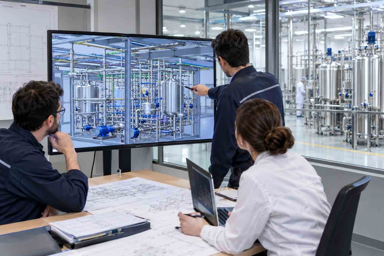
In industrial facilities, process pipelines share limited spatial envelopes with structural steelwork, HVAC ductwork, cable trays, equipment, and the building structure itself. In piping systems designed using two-dimensional drawings, interference between these elements is often discovered only during site installation. This results in costly rework, project delays, and unexpected budget overruns. 3D piping design and clash detection resolve these spatial conflicts on the drafting table before installation begins. In this article, we examine how 3D design contributes to overall project success.
What is 3D Piping Design?
3D piping design is the process of modeling pipelines, valves, process equipment, and support structures in three dimensions using their true physical dimensions. The model incorporates precise pipe diameters, fitting dimensions, slopes, valve locations, and connection details. It translates the functional logic of the P&ID into a physical, spatial arrangement.
Modern design software automatically incorporates standard fitting dimensions and material specifications as lines are routed. Consequently, the 3D model becomes an accurate digital twin of the materials dispatched to the site.
What is Interference and Clash Detection?
Clash detection is the automated process of checking whether different elements within the 3D model occupy the same physical space. Software algorithms identify hard clashes—where pipelines intersect with structural steel, equipment, ductwork, or civil structures—as well as soft clashes, where required clearance zones for operation, maintenance, or thermal expansion are compromised.
Typical Issues Encountered On Site
- Pipelines routing directly through structural beams or columns
- Valve actuators colliding with adjacent walls, structural elements, or neighboring lines
- Pumps or heat exchangers positioned without sufficient clearance for maintenance removal
- Sloped lines losing required pitch when crossing under adjacent pipe racks
- Cable trays sharing routing envelopes with high-temperature or wet process lines
- Point-of-use valves installed out of reach of operators
When identified on site, each of these issues typically requires field cutting, re-welding, and additional material procurement. In hygienic piping systems, every additional weld introduces extra inspection, documentation, and qualification burden.
Importance of 3D Design in Hygienic Piping
In hygienic piping systems, continuous line slope is essential to ensure complete drainability and prevent liquid stagnation. Verifying continuous pitch along complex spatial routings is difficult using 2D drawings. In a 3D model, line slopes, elevation changes, and low points are visually explicit and measurable. Branch lengths can be verified directly against strict dead-leg limits. Hygienic design principles are thereby validated prior to fabrication.
Isometric Drawings and Bills of Materials
A primary output of the 3D model is the automated generation of piping isometric drawings for individual line spools. Isometrics detail cut lengths, fitting and valve positions, weld locations, and itemized material lists. Construction teams rely on these drawings for field assembly, weld mapping, and quality tracking. Bills of materials (BOM) extracted directly from the model streamline procurement and minimize material surplus or shortages.
Pre-fabrication Opportunities
A fully verified 3D model enables off-site shop pre-fabrication of major piping spools. Welding performed in controlled workshop environments offers higher quality control, safer working conditions, and faster execution compared to field welding. Minimizing on-site welds reduces installation schedules and limits disruption in operational production facilities. Our shop fabrication capabilities rely on this integrated approach.
Maintenance Access and Operator Ergonomics
Beyond facilitating installation, 3D models allow project teams to evaluate long-term operations and maintenance accessibility. Valve handwheel heights, clearance envelopes for pulling filter elements or pump impellers, instrument display visibility, and maintenance access walkways are reviewed within the digital environment. Involving plant operations and maintenance teams in 3D design reviews prevents operational bottlenecks after handover.
Design in Existing Facilities Using 3D Scanning
For expansion or modernization projects within operating plants, accurately modeling existing infrastructure is critical. Legacy paper drawings often fail to reflect as-built conditions. 3D laser scanning generates precise point cloud data representing the exact physical geometry of the existing plant. Designing new piping within this point cloud context ensures highly accurate clash detection.
3D laser scanning can also document as-built conditions following installation completion. Updating the digital model to match minor field modifications ensures future facility modification projects begin with an accurate, reliable baseline.
How Design Reviews are Conducted
The full benefit of 3D modeling is realized through structured design reviews. In a typical project, model reviews are conducted at 30%, 60%, and 90% design completion stages with stakeholders from process, mechanical, electrical, automation, operations, and quality disciplines. Action items identified during each review are tracked to resolution before advancing to the next milestone, ensuring issues are resolved early when engineering changes carry minimal cost.
Design Supported by Flow Analysis
3D piping models become even more powerful when combined with hydraulic calculations and Computational Fluid Dynamics (CFD). Hydraulic line sizing, pump head verification, and clean-in-place (CIP) wall shear stress velocities can be validated during the design phase. SS Proje incorporates this methodology in our 3D design and flow analysis with SolidWorks Routing services.
Frequently Asked Questions
Is 3D design necessary for small-scale projects?
While not strictly mandatory for every small scope, 3D design provides substantial value in tight spaces, retrofit environments, or projects involving hygienic piping standards. Preventing a single major field clash typically offsets the cost of 3D modeling.
Is the 3D model handed over to the client upon project completion?
Yes, depending on contract deliverables. In most projects, the finalized as-built 3D model is provided as part of the project turnover package, serving as an asset baseline for future facility management and modifications.
When should clash detection be performed?
Clash detection should be conducted iteratively throughout the design phase, concluding with a comprehensive final verification run prior to releasing isometric drawings for spool fabrication.
3D piping design and clash detection represent the most reliable method for resolving spatial installation issues on the drawing board rather than on the construction floor. An accurate 3D model delivers faster installation schedules, reduced rework, verified hygienic design compliance, and ergonomic maintenance access. Contact us to discuss your 3D piping design requirements with our engineering team.